There is a very common problem with the Super Nintendo where the DC connector cracks of breaks off. The problem is, the SNES uses a proprietary type of plug and it is molded into the back plate. I haven't been able to finds a direct replacement without having to replace the entire plate, which is a little expensive... Ok it's like 12 bucks, but I'm cheap.
Anyway, I got a few like this from a buddy of mine to fix for him, so I figured I could show you the cheaper alternative. I say cheaper, but it really depends on what you have already... I'm modding this one to take a Sega Genesis/NES power supply, so if you didn't already have another power supply you'd have to buy one, but I have a ton of these things laying around, so no big deal.
This one had a crack in the center hole, so it would cut out while playing randomly. It's a little hard to see, but it's there.

To get started, you have to take the main board out:

Here's a better look at the back panel assembly:

You have to de-solder the connections to get it loose:
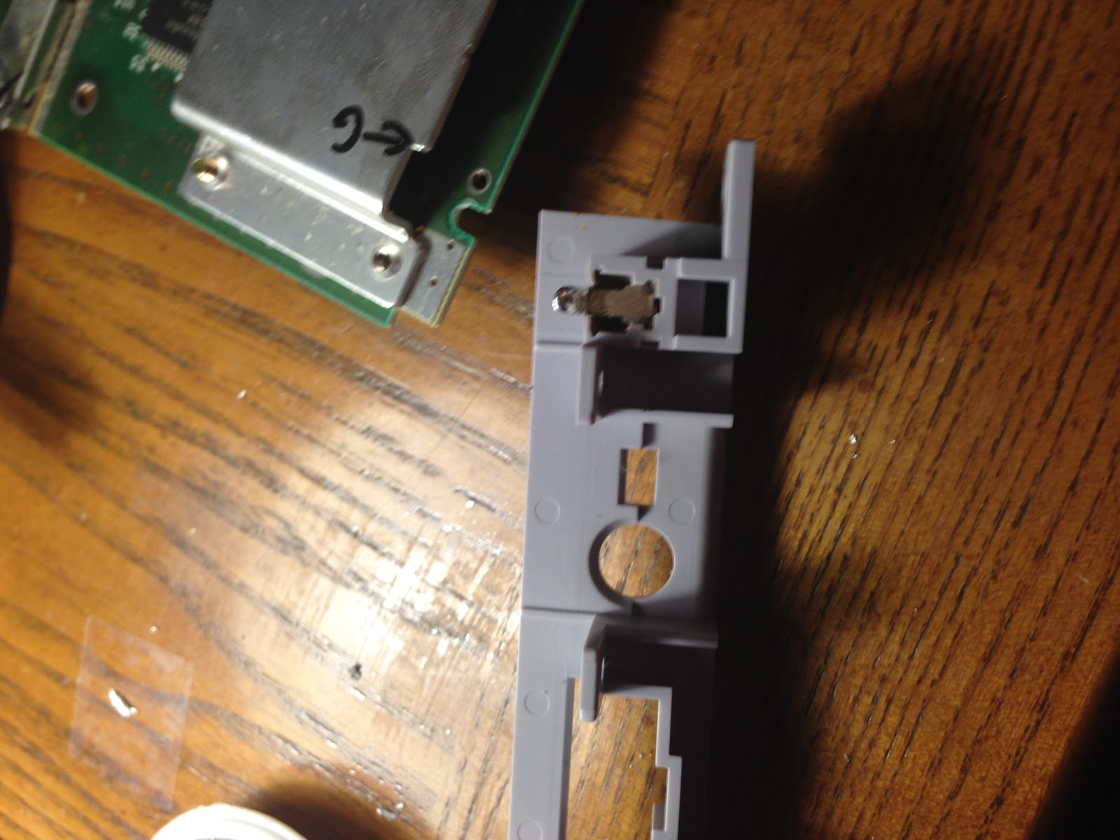
View from the bottom:

Here's the board with the panel removed, from the bottom. This is where we'll be soldering the new plug leads on to.

After removing the electrical connections, you need to remove a lot of material to make room for the new plug. Make sure not to mess up the tabs with the screw holes on them.

The main goal here is to cut down to a flat surface for the new plug to mount to, so that it mounts flush and sits evenly.

Here's the plug mounted up:

With the leads soldered on,

****Note that you should solder the leads on to the plug before you install it.***
I've seen a few ways to route the wires when doing this, but I liked this nice gap beside the main fuse, so I fan them through there:

FYI: The red is positive and connects to the sleeve, the black is negative and connects to the tip.
Here's a side view of the installed assembly.

That's pretty much it, button it back up and viola:

If you do it properly, it almost looks like it was factory installed.
This plug I'm using here is from Radio Shack P/N: 274-1582, which is around 4 bucks. This works perfectly with the Genesis 1 power supply of the factory NES power supply. You could also use a universal, but you want to make sure it can run 10V at at least 800MA.
Thanks for reading!
The SNES Mini is a cute little machine, that I haven't really dealt with much until recently. I was asked to repair the power jack on this guy as well, so I figured I would show you guys some of the internal differences.

You'll notice first off that the board is much smaller, but it's more than that. They also integrated the controller ports and power switch, rather than having daughter boards for them.

One of the bigger differences is that, at least with this specific model, is that they took out the RF connection and rearranged the ports on the back side. (If you look at the board it looks like thet left space for the RF box, but it's not there on this guy) This rearrangement means that the reproduction replacements I mentioned in the previous article won't work on the mini's. I spent a few hours trying to see if such a thing existed with no luck... I really wanted to keep a factory look on this one, but it just isn't possible. (If anyone finds a port for the mini PLEASE LET ME KNOW)
Anyway, you can see the broken port below and how different this is from the standard SNES:

It doesn't have those annoying mounting screw holes to worry about, which is a relief:

My local Radio Shack was out of stock of the connector I've been using for these guys, so I grabbed a different one with the same plug type. It turns out to be substantially bigger than what I'm used to. The one I usually use fits inside the factory hole...

A little cutting and melting plastic later I got it in there:

From the back side:

It was actually a little easier to get the wires installed in this one. You don't have to run the wires around the side. There is a ton of room in there lol

Anyway, electrically this works exactly the same as the standard SNES and it booted up beautifully!
That's all for now, I hope you enjoyed it.
So I picked up this Gameboy Advanced specifically for this project. I love the form factor of the GBA but the screen not being backlit is a dealbreaker. On the other hand, I love the screens in the GBA SP, but my hands are huge and it is terrible uncomfortable for extended use. So why not have the best of both worlds? (I'll refrain from singing some Hannah Montana here...) I found a guy from China who makes a ribbon cable to do just that. Zerey Zhang is one of the nicest guys I've done businesss with and I highly recommend his work. I should note though that rosecoloredgaming.com makes a kit to do this and they have some excellent documentation as well.
So let's get started:
Here are some pictures from the teardown:


So I got this thing used for cheap, but with cheap game systems comes gunk...

I have a special toothbrush that I use for exactly this lol. I like to use a little dish soap solution to clean parts like this. It works fantastically to get old soda and skin cells off of the plastic and rubber bits. But for cleaning contacts and metal things, I prefer to use 'blue glass cleaner'.

So the screen from the GBA SP has a larger frame than the old GBA, so you have to cut down a few ledges that supported the original screen. I forgot to take a before picture here, but you can see my cuts pretty well. I used a combination of a utility knife, pliers, and some wood-carving chisels to smooth it out.

Checking the fit:

Old screen vs new screen:

The screen has 2 brightness settings, depending on what voltage you connect it to. With that in mind, I decided to add in a toggle switch to go between the two settings.
I used one of my 'hot knife' tips for my soldering iron to make the hole here, then I cleaned it up with an Xacto knife.

I secured the switch using some of the scraps of plastic from the screen scrapings. I welded the plastic in with my 'hot knife'. I've stated before that I don't recommend doing this and I'll stand by that. I've got a lot of practice at this, so it's rare that it catches fire, but it does happen and it pretty much ruins whatever you're working on so don't do it!

The switch from the outside:

Wiring it up:

I didn't take pictures of the other wires for some reason...
Anyway, here is the cable I got from Zerey:

To make up for the length of the cable, you need to put a little fold into the SP's ribbon cable:

The screen hooked up:


So after I got this all hooked up something ended up being wrong with the screen... I did get it to come one once and I took a picture of it:

It turned out that the screen was defective, so I sent it back in. I haven't gotten around to re-ordering a new one yet. I am planning on ordering a new one next week, but we'll see what the budget allows...
That's it for now, I'll keep you posted when I get some more work done on this.
UPDATE
I've long since finished the build for this, but I didn't do any proper documentation. So to make up for it, I've made a video showcasing it on my YouTube channel.
So I found this gem yesterday and I just couldn't pass it up. It was in mint condition and in the original box and very reasonably priced (ie way less than ebay) Seriously, this thing looks like it had never been used and if it weren't for the rubber bands tying the cables and the wear on the styrofoam, I would have thought it had never been out of the box!

So what better to do with a mint condition console, than take it home and modify it?
Yes I'm serious :)
I also picked this up while I was out yesterday:

But wait! Famicom games won't play on US Consoles right? It turns out they do, with very little modification.
So here's a quick overview of how to make a US Super Nintendo play Japanese Famicom games
The only thing keeping this from working are two little tabs in the bottom of the cartridge slot to keep it from plugging it in. Here's one side:

So all you have to do is to get these little buggers out of there. I found a really great guide on instructables to teardown and reassemble the whole console to get to the tabs, but it would take a few hours and I figured I could just do this:

I ended up using a smaller pair that were a bit sturdier to ply them back and forth until they snapped right off:

And poof! No more tabs!

The other side:

This took all of five minutes and I didn't even turn a screw...
Viola, my region free SNES :)

Powering it up for the first time: (please ignore the Caytee foot in the picture)
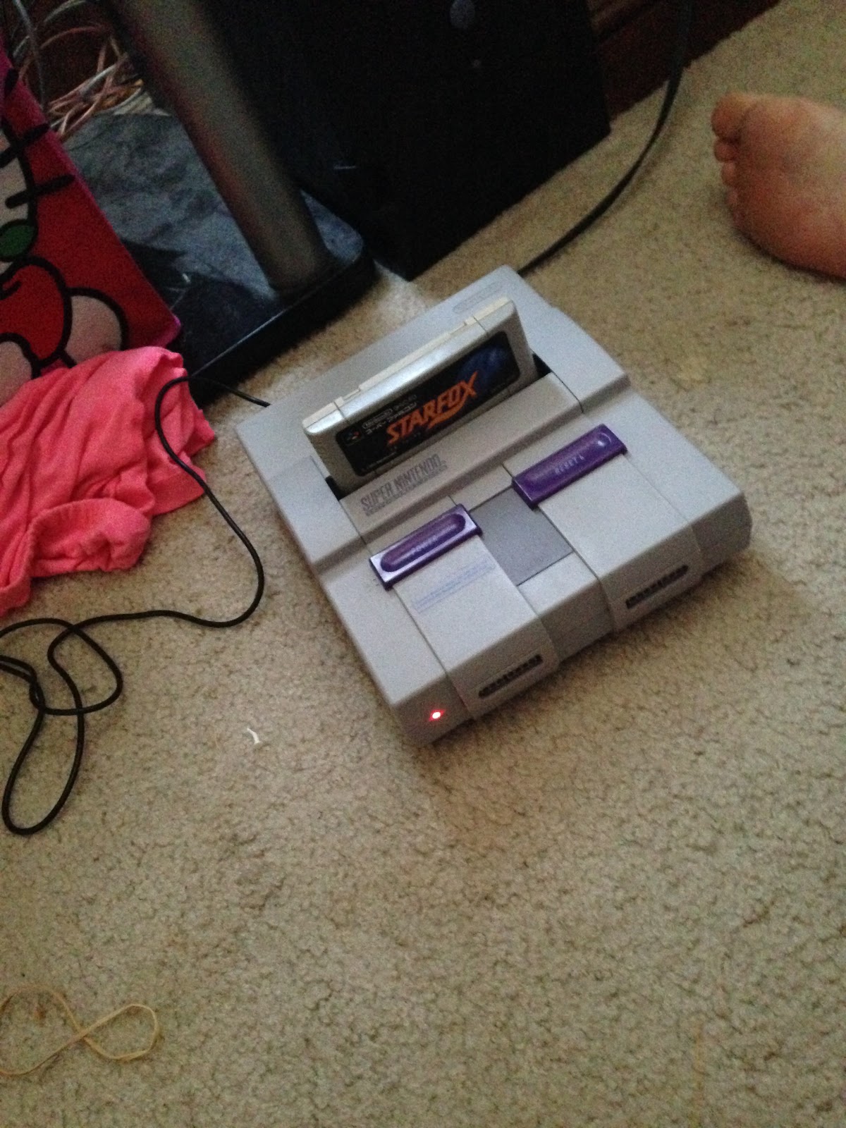
Japanese Starfox playing on the TV:

My little helper failing horribly at Starfox... She's even worse at DDR

That's it for now! Thanks for reading!
So a long time ago, probably 2005 ish, I modded my old GameCube to play Japanese games. It was a tremendously difficult task, as I had neither the tools or experience at the time to undertake such a task. It worked, but it would randomly short out and cause the system to reboot and was held together by rubber bands, because I had misplaced the case screws. Unfortunately, that old guy bit the dust last year and, despite my best efforts, I was unable to salvage it.
About 3 weeks prior to it's demise, I ran across this gem at Goodwill and it was too good of a price to pass up, not knowing I would actually need it so soon.

Sadly, I haven't really used it since I picked it up; I mean, I hooked it up and made sure it worked, but that's about it. These days, I don't have the time to game very often and I only have 2-3 games for the GameCube. Of those, the only one I've been really wanting to play is in Japanese and I haven't had the free time to hack into it.
Until now!

I won't go into details of the actual mod itself, it's pretty straightforward and well documented elsewhere. If you're interested I used this guide's technique. I should note, this model's internals were quite different from my first one's. I reason that there are at least two styles of boards used on these systems. Most notably different, my original GC had a port on the back marked "digital out" (or something to that effect) in addition to the A/V port, whereas this one has the A/V only. This guide matches my older GC's internals and has different wiring points accordingly.

Here I have the slider switch wire up and ready to go. I took some measurements and fit the switch in between the memory card slots, for easy access. I didn't like the idea of having to pull it out of the cabinet to change the region on the back side of it. Call me lazy, but I like it better this way :)

Here is the switch close up and hot-glued in place. I did have to do some slight modification to the memory card sockets themselves to make room for the housing of the switch, but it was very minor and not really picture-worthy, but still worth mentioning.

Here we are all buttoned up and plugged in, ready to test it all out.

It booted up splendidly in English. Power it down, flick the switch, and viola:

Japanese!
And for one last touch, while I was playing around inside there I figured I'd have some fun with it and did this:

I've had this pink LED laying around for like 3 months now, left over from another project, so I gave it a new home. It does look a lot better in person, but I'm no photographer so this is the best you're getting :)
Now, you may be wondering why I would go through all this just to play a game in Japanese. Especially, since I have a modded Wii that can do that already. Well, the simple fact is that the Wii won't read my Japanese formatted GC memory card and I have entirely too much time invested in it to reformat it and start over.
I have more in store for this little guy in the future, but I'm still pretty undecided about what, exactly, to do with it. I am planning on transplanting it into something else, like I did with the N64. I have no idea what to put it in though... Any suggestions?
No comments:
Post a Comment