Update #1
Update #2
Update #3
Quick Update!
So after dismantling the iMac for my main project, (part one XD) I couldn't help but think about how much of a waste it was to just toss the original guts of the machine. Especially, since it worked perfectly before I took it apart...
So I decided to build a new case and actually use the thing! I am a loooong way from being done with this, but I have enough work to, at least, show what I'm working on.
I started by constructing a rudimentary frame for the CRT:

Basically, I just took some scrap wood I had laying around and went to work. It's not pretty, but it;s very solid. I am going to add on a tilting mechanism to this at a later stage, so that the monitor can be moved up or down for the best viewing angle.
When I separated out parts for each of these projects, I deemed that the power plug needed to stay with the shell. This meant I needed to come up with a solution to power this guy. I took the easy route and soldered in an old power cable I scrapped off a heater I saw in a dumpster when I was moving... For the record, no I didn't actually go into a dumpster, it was on the ground6 beside it when I took my trash out lol

The cable soldered in; when the final case design is finished I am going to add a relief to it so it can't be yanked out.

Here, I've mounted the power supply board to some chip-board and a 2x4. The logic board will be simillarly mounted on the opposite (top) side, but I have a goo bit of wiring to do, and a heat-sink to find, before I am ready to mount it up too.
Here's a top view of the power board mounted:

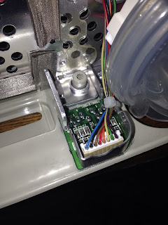
The next issue I ran into, was this weird plug here, which needs to stay in the original shell. It has the wiring for the case LED's speakers, power button, microphone, and headphone jacks.

Here is the other side of the plug:

So my challenge was to take this poorly documented plug and interface my hardware into it. It's every hacker's dream right? Anyway, I found this guide which shows how to interface with a standard ATX power supply, so it leaves out some of the vital information I need to make this happen. For example, which of the speaker pins are +/- and left or right, or how the LED's connect to the pins they have labeled 'LED'...
So I did some more digging and found the LED and power switch are beautifully labeled:

The headphone jacks are not so well documented lol. I decided to save that for later, because each of the ports has a left, right, ground, and "sense" lines, and I was feeling lazy that day lol.
Anyway, I have some lovely notes that I'll add when I get them prettied up... (my handwriting is terrible)
I salvaged these guys from my old PC tower I threw out after I stole the power supply:

I have a power switch, standby LED, and a power LED that I'm interfacing with the logic board. Luckily, they have these lovely female header pins on them. So I rewired the headers to match the pin-out that I needed, and soldered the ground wires all together.

These fit perfectly into the female header on the logic board.

Note that these are not the actual pin connections, but just to show the concept. I am so tempted to plug it all up and see if my LED's and buttons work, but it would be so dangerous and I would have to discharge the CRT again. It wasn't that hard, but it's pretty dangerous and I don't feel it's worth it just to test an LED or two...
That's it for now, stay tuned for future updates! I've got a lot of big things planned for this guy, so stay tuned!
~~~~~~~~~~~~~~~UPDATE #1~~~~~~~~~~~~~~~

Here I've attached one of the side-support blocks, which I am going to mount on a pivot, so the screen will be able to tilt. You can also see the fan I mentioned earlier. That's not where it's going, at least, I don't think so...

The next thing I had to do was to attach the heat-sink. Here is the big guy close up:

I scratched it up a little bit when I was cleaning the old glue and compound off of it. It's not a big deal, seeing w all of this gets smothered in compound and stuck to the CPU.

The heat-sink compound applied and ready to go:
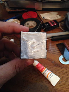
And it's attached! This heat-sink should be more than enough for this little 300 MHz processor. The original heat-sink was simply a block of aluminium attached to the metal separator plate between the boards, so this should do nicely.

That's all for now, I've got a few more steps before I am ready to boot it up, or finish framing it in, but as soon as I do, I'll update it here!
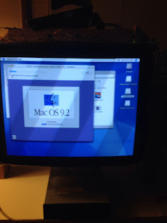
IT'S ALIVE!!!!!!!
...as long as I keep my hand right here...

I got this guy up and running today, after chasing down a few wires and properly grounding a few things I hadn't considered before. Since I don't have the threaded holes for this port to screw in to, I have to hold it just so to get the monitor to turn on...

To resolve this, I simply took a piece of string and fastened it in place. It's no zip-tie, but it does the job :)
Anyway, here's the "About this Mac" from this old thing once I got it booted. Sorry about the quality, but I couldn't get a screenshot yet.

That's it for now! More once I get the frame further along!
Alright cool new stuff happening with this build!
I think this update will be mostly show and tell, there's not much to say and a lot to see.
First off, I made some legs for this contraption:

I mounted the legs to this board underneath to keep everything lined up and add some stability.

I am pleased to say, it rotates very well! It will go about 10° forward and backward about 270°, not that you would ever go that far lol.
Here's a shot of it tilting back a bit:

From the other side:


Here's a shot from the top. The hard drive is kinda just sitting on top too. I have to make a frame to hold it up there still.
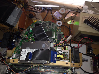
Here's a few other shots:


I haven't hooked in the dvd drive yet, but that is where it's going to end up when I'm done:

Booting up "Classic mode" lol I had totally forgotten about this feature :) It's been like 9 years since I've used it, but I had good reason.
.
.
.
.
.
wait for it:
.
.
.
.
.
.

And I just nostalgia'd all over myself :)
I have a lot more planned for this build, but this is where I'm going to stop for now. The rest of this build is going to be quite expensive and time consuming. So basically, it's on hold until I get a new job, or at least a second one.
I had a small problem with the heatsink not wanting to stay on the processor once I got the board upside-down. It would seem like it was sticking on, then a few hours later it would be laying behind the computer...
So I came up with this:

I took some copper wire and made a little heatsink-hammock for it. It isn't the prettiest thing I've made, but it's certainly not the ugliest lol. It keeps the heatsink strung tightly against the processor and, so far, keeps it pretty cool :)
Thats all for now, Ill post more as I get to it!
No comments:
Post a Comment